🧬 Verilog Data Types, Logic Values, Arrays & Net Types #
Verilog provides a variety of data types and signal states for modeling hardware behavior, both in simulation and synthesis. This section covers the most common types, how logic works in 4-state simulation, and how to structure data using arrays and module instances.
📦 Common Verilog Data Types #
| Type | Category | Signed? | Default Width | Initial Value | Usage Example |
|---|---|---|---|---|---|
wire |
Net (combinational) | No | 1 bit | x |
Continuous assignment |
tri |
Net (tri-state) | No | 1 bit | z |
Shared bus / tri-state |
wand |
Wired-AND net | No | 1 bit | x |
Multiple drivers (AND) |
wor |
Wired-OR net | No | 1 bit | x |
Multiple drivers (OR) |
reg |
Variable | No | 1 bit | x |
Procedural assignment |
integer |
Variable | Yes | 32 bits | 0 |
Loop counters, calculations |
real |
Variable | Yes | 64-bit float | 0.0 |
Simulation-only math |
time |
Variable | No | 64 bits | 0 |
Simulation time tracking |
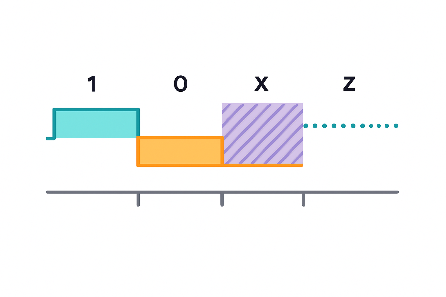
🔢 Verilog Logic Values #
Verilog uses a 4-state logic system where each bit can represent more than just 0 and 1:
| Value | Name | Meaning |
|---|---|---|
0 |
Logic Zero | Driven low (active logic 0) |
1 |
Logic One | Driven high (active logic 1) |
x |
Unknown | Conflict or uninitialized |
z |
High Impedance | Not driven / floating — e.g., tri-state bus |
⚠️
xandzvalues are critical for debugging and modeling bus behavior in simulation.
🧠 Example #
reg a = 1'b1;
reg b = 1'bz;
reg c = 1'bx;
reg d = 1'b0;
a: logic highb: high impedance (undriven)c: unknown due to conflict or missing assignmentd: logic low
📏 Scalar vs Vector #
🔹 Scalar #
- A single-bit signal (default when no width specified)
wire enable; // 1-bit scalar
🔹 Vector #
- A multi-bit signal — typically used for buses or grouped bits
wire [7:0] data_bus;
reg  [3:0] nibble;
📚 Arrays in Verilog #
Arrays enable grouping of signals, memory structures, register files, and multi-instance modules.
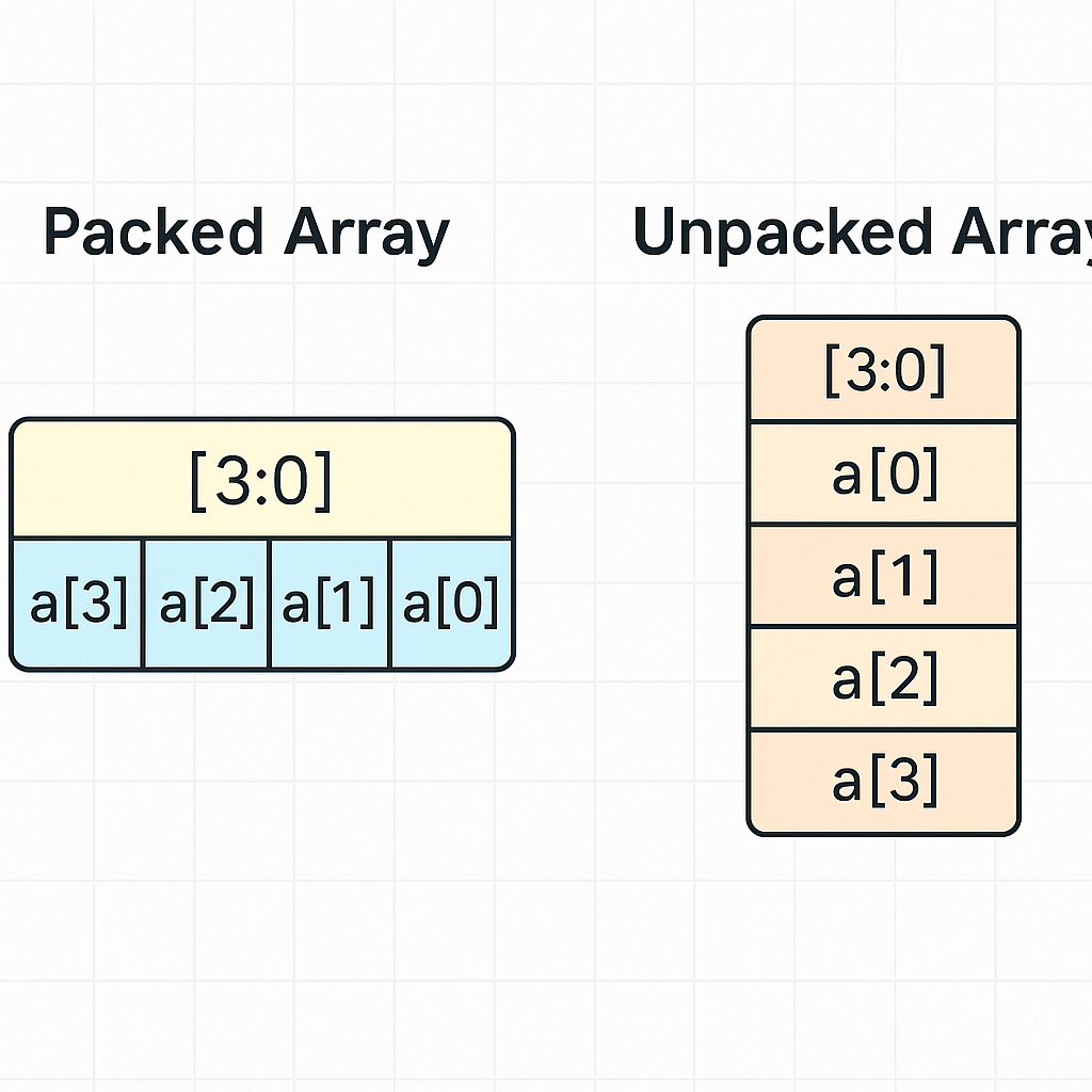
🔹 1. Packed Arrays (Bit-Vectors) #
A packed array represents a fixed-width vector.
reg [3:0] my_bus;
Example: #
my_bus = 4'b1010;
$display("Bit 2: %b", my_bus[2]); // Output: 1
🔹 2. Unpacked Arrays (Memory Style) #
Used to model RAM, ROM, or lookup tables.
reg [7:0] memory [0:255];
Example: #
initial begin
  memory[0] = 8'hFF;
  memory[1] = 8'hA2;
end
🔹 3. Multidimensional Arrays #
Supported since Verilog-2001. Commonly used in image buffers, matrices, and cache designs.
reg [7:0] image [0:63][0:63]; // 64x64 grid
🔹 4. Array Initialization with Loops #
integer i;
initial begin
  for (i = 0; i < 256; i = i + 1)
    memory[i] = 8'h00;
end
🔹 5. Array of Module Instances #
Verilog allows generate blocks to instantiate repeated hardware structures:
genvar i;
generate
  for (i = 0; i < 4; i = i + 1) begin : gen_block
    my_module u_inst (
      .in(in[i]),
      .out(out[i])
    );
  end
endgenerate
🔹 Vector Bit-Select and Part-Select Addressing #
Allows accessing individual bits or ranges (slices) within a vector signal.
a[3]      // Bit-select: accesses bit 3
a[7:4]    // Part-select: accesses bits 7 down to 4
Useful for manipulating specific bits of buses or registers.
🔹 Assignments and Truncation #
When assigning between vectors of different widths, extra bits are truncated or padded with zeros.
reg [7:0] a;
reg [3:0] b;

a = b;      // Zero-padded to fit 8 bits
b = a;      // Truncated to lower 4 bits
Truncation can lead to data loss if not handled carefully.
🎯 Array Types Summary #
| Array Type | Description | Use Case |
|---|---|---|
| Packed Array | Bit-vectors | Ports, buses, logic operations |
| Unpacked Array | Indexed storage of elements | RAM, register file |
| Multidimensional Array | Matrix of elements | Caches, images, framebuffers |
| Array of Instances | Multiple module instantiations | Pipelining, parallel structures |