🔧 What is Verilog? #
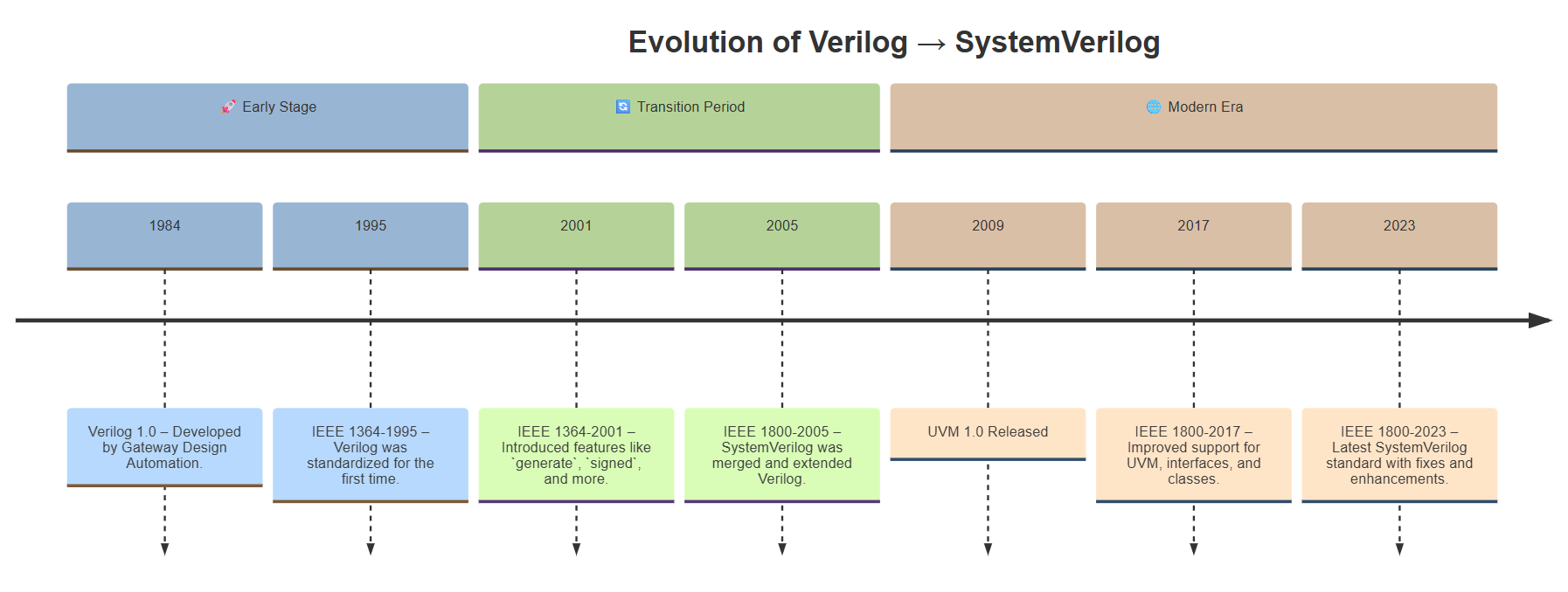
Verilog is a Hardware Description Language (HDL) designed to describe, simulate, and implement digital electronic systems — from simple logic gates to entire processors. Originally developed in the 1980s by Gateway Design Automation and later standardized by IEEE as IEEE 1364, Verilog enables designers to describe hardware circuits using a textual, programming-like syntax.
Unlike traditional programming languages that execute on CPUs, Verilog describes circuits that are synthesized onto physical hardware like FPGAs or ASICs. It allows designers to model:
- Logic gates and combinational circuits
- Sequential logic (like flip-flops and registers)
- State machines
- Complete processor architectures

🕰️ What Came Before Verilog? #
Before Verilog, digital hardware was typically designed using schematic entry tools and low-level hardware description languages like:
- Switch-level modeling or transistor-level schematics, which required describing circuits gate-by-gate or even transistor-by-transistor.
- ABEL (Advanced Boolean Expression Language) – used mostly for PAL and CPLD programming in the early 1980s.
- PALASM (Programmable Array Logic Assembler) – one of the first hardware languages used to describe logic equations for PAL devices.
- VHDL (VHSIC Hardware Description Language) – developed by the U.S. Department of Defense in 1981 as a more formal HDL, and standardized as IEEE 1076 in 1987.
Note : VHDL was more verbose and strongly typed, whereas Verilog offered a more concise and C-like alternative, especially for RTL modeling.
🚀 What Did Verilog Bring to the Table? #
Verilog introduced a C-like, concise syntax that made hardware design more approachable and readable compared to older HDL languages like VHDL or schematic-based workflows.
Key contributions of Verilog:
- ✅ RTL Modeling: Simplified Register Transfer Level design using
always,assign, andinitialblocks. - ✅ Mixed Abstraction: Allowed both behavioral and gate-level descriptions.
- ✅ Modular Design: Supported module-based hierarchical design, encouraging reusable components.
- ✅ Widespread Tool Support: Quickly adopted in industry thanks to simplicity and synthesis compatibility.
💻 What is an HDL (Hardware Description Language)? #
An HDL is a programming-like language used to model and describe the behavior and structure of digital circuits. Popular HDLs include Verilog and VHDL. Unlike software, HDL code is intended to be synthesized into real hardware on FPGAs or ASICs.
🧠 HDL vs. Software Languages: What Makes Verilog Different? #
At first glance, Verilog may look like a programming language – it uses if, case, for, and semicolons. But in reality, Verilog is fundamentally not a software language.
Here’s how HDLs like Verilog differ from traditional programming languages such as C, Java, or Python:
| Feature | Verilog (HDL) | C / Python / Java (Software) |
|---|---|---|
| Execution Model | Event-driven, parallel | Instruction-driven, sequential |
| Time Awareness | Time is explicit (#10, @posedge) |
Time is implicit or nonexistent |
| Output Behavior | Describes hardware connections | Computes software behavior |
| Concurrency | Multiple blocks run simultaneously | Code executes one line at a time |
| Final Destination | Mapped to silicon (FPGA/ASIC) | Runs on CPUs or VMs |
Verilog simulates real-world circuits. It doesn’t just “run” — it waits for events, reacts to signal changes, and models physical timing.
This event-driven nature is what makes Verilog powerful yet different. For example:
always @(posedge clk) begin
  data_out <= data_in + 1;
end
This block only triggers when clk has a rising edge, not sequentially like software. That’s why understanding time, delay, and signal sensitivity is essential in HDL design.
⚡ Software vs. Hardware Mindset: A Simple Comparison #
Understanding the difference between sequential software execution and concurrent hardware description is essential when learning Verilog.
Let’s compare a simple example:
👨💻 Software Perspective (C code – sequential) #
int a = 5;
int b = a + 3;
In C, the CPU executes these lines in order. First, it assigns 5 to a, then calculates a + 3 and stores the result in b. Once executed, these values stay constant unless explicitly changed later in the code.
🔌 Hardware Perspective (Verilog – concurrent) #
assign b = a + 3;
In Verilog, this is not a one-time execution. Instead, it defines a continuous assignment:
Whenever
achanges,bautomatically updates in real-time — as if a wire is connecting them.
There’s no instruction pointer. No order of execution. Just signal propagation, like in actual circuits.
🧠 Key Insight: #
| Concept | Software (C) | Hardware (Verilog) |
|---|---|---|
| Time | Implicit | Explicit and reactive |
| Flow | Line-by-line | Parallel and event-driven |
| Variables | Store values | Represent signals or nets |
| Assignment meaning | Immediate computation | Persistent relationship between signals |
🔁 In hardware, you’re not executing instructions, you’re describing behavior that happens in parallel — driven by time and events.
Once you grasp this, the whole Verilog world starts to make sense.
💡 Tip for Beginners #
Don’t treat Verilog like C or Python. Instead:
- Think in terms of hardware structure, not software flow.
- Ask yourself: “What real hardware am I describing?”
- Master the concepts of time, edge, and signal dependency.
Once you make that mindset shift, Verilog becomes a powerful design tool.