
🧠 Hardware Design Abstraction Levels#
Hardware design can be described at multiple levels of abstraction. At the highest level, the system’s overall functionality is defined, while the lowest level shows how individual transistors are connected.
1️⃣ Architectural Level (Highest)#

What does it describe?: Defines the system-level features and specifications
Examples:
- “Design a 32-bit processor”
- “Include 1MB of cache memory”
2️⃣ RTL (Register Transfer Level)#

- What does it describe?: Describes how data flows between registers
- Example Verilog Code:
module counter(
  input clk,
  output reg [3:0] count
);
always @(posedge clk)
  count <= count + 1;
endmodule
3️⃣ Gate Level#
- What does it describe?: Shows logic gates (AND, OR, NOT) and their interconnections
- Example:
module top_module (
    input  a,
    input  b,
    input  d,
    input  clk,
    output out,
    output q
);

    AND2X1 U1 (
        .A(a),
        .B(b),
        .Y(out)
    );

    DFF U2 (
        .D(d),
        .CLK(clk),
        .Q(q)
    );

endmodule
module AND2X1 (
    input  A,
    input  B,
    output Y
);

    assign Y = A & B;

endmodule
module DFF (
    input  D,
    input  CLK,
    output Q
);

    reg Q_reg;
    assign Q = Q_reg;

    always @(posedge CLK) begin
        Q_reg <= D;
    end

endmodule
4️⃣ Transistor Level#

- What does it describe?: Describes how individual transistors are connected
- Used for: Custom-designed circuits (e.g., SRAM bitcells)
- Example: CMOS inverter design
5️⃣ Physical Layout (Lowest)#
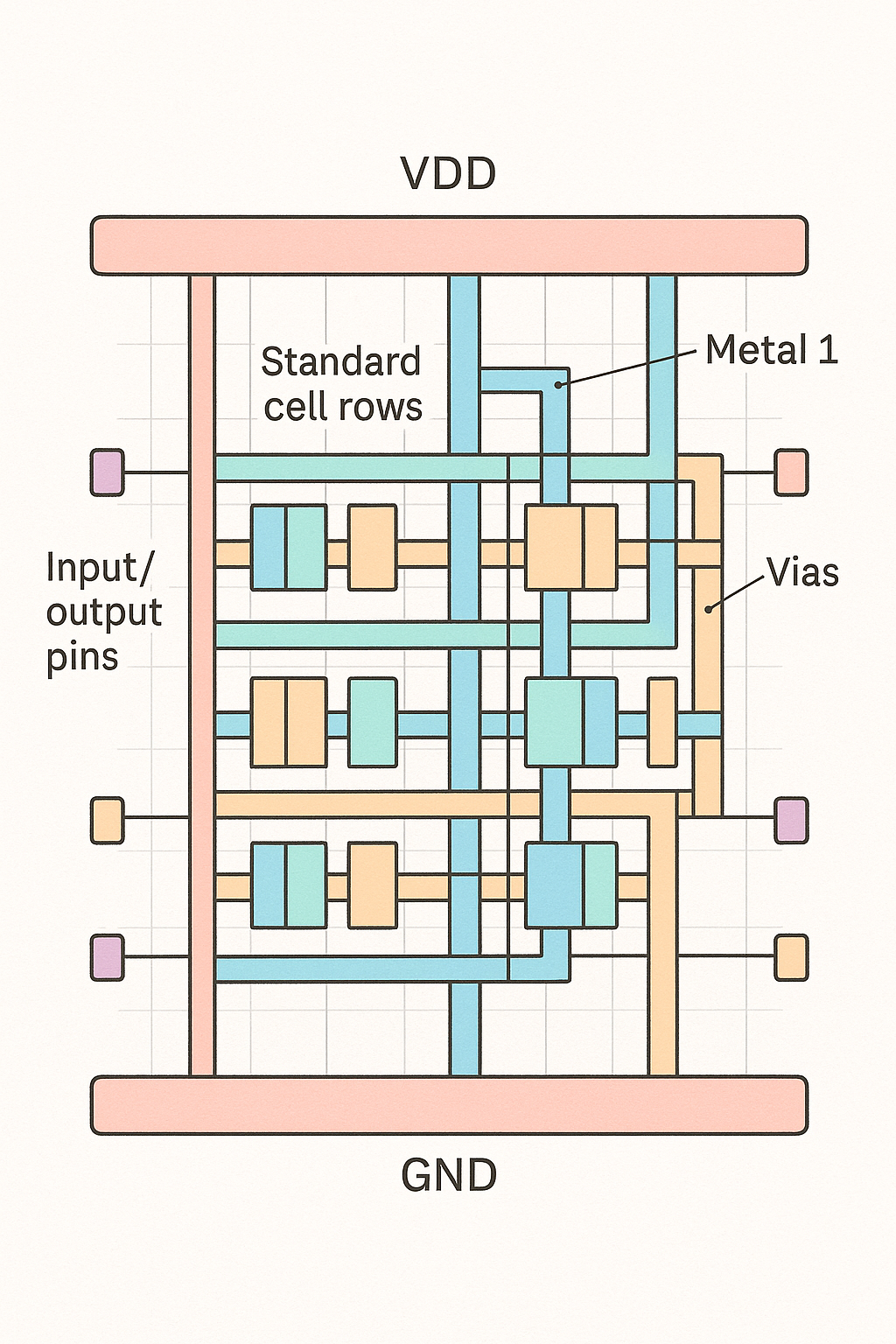
- What does it describe?: Specifies the physical placement of components on the silicon chip
- Output: GDSII file for fabrication